Part 1: Digital I/O with LED’S
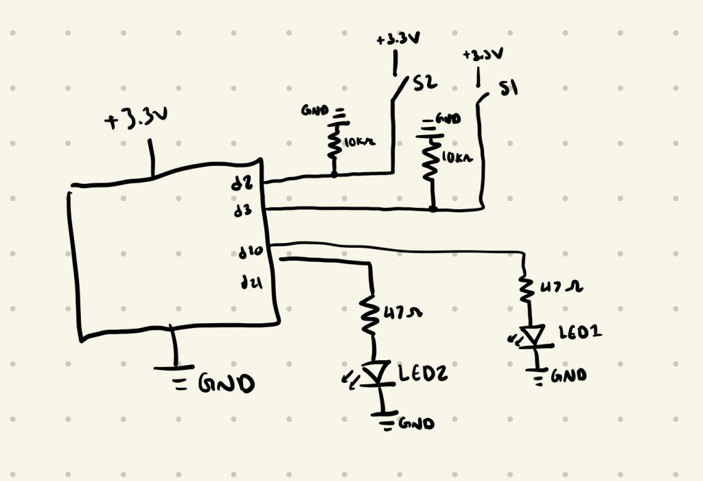
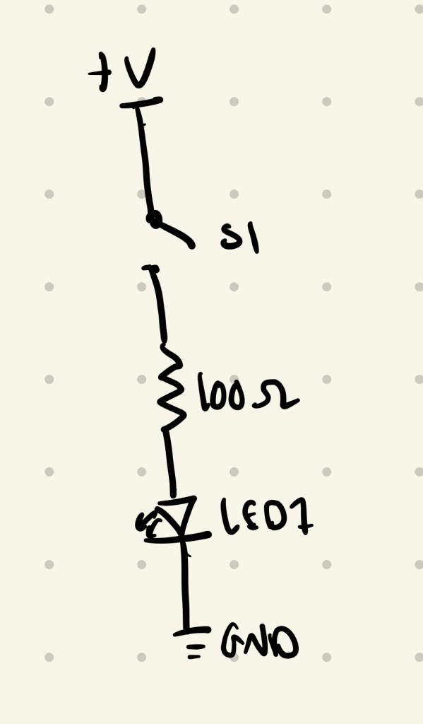
I started by calculating what resistor values I would need for the LED’S using Ohm’s Law:

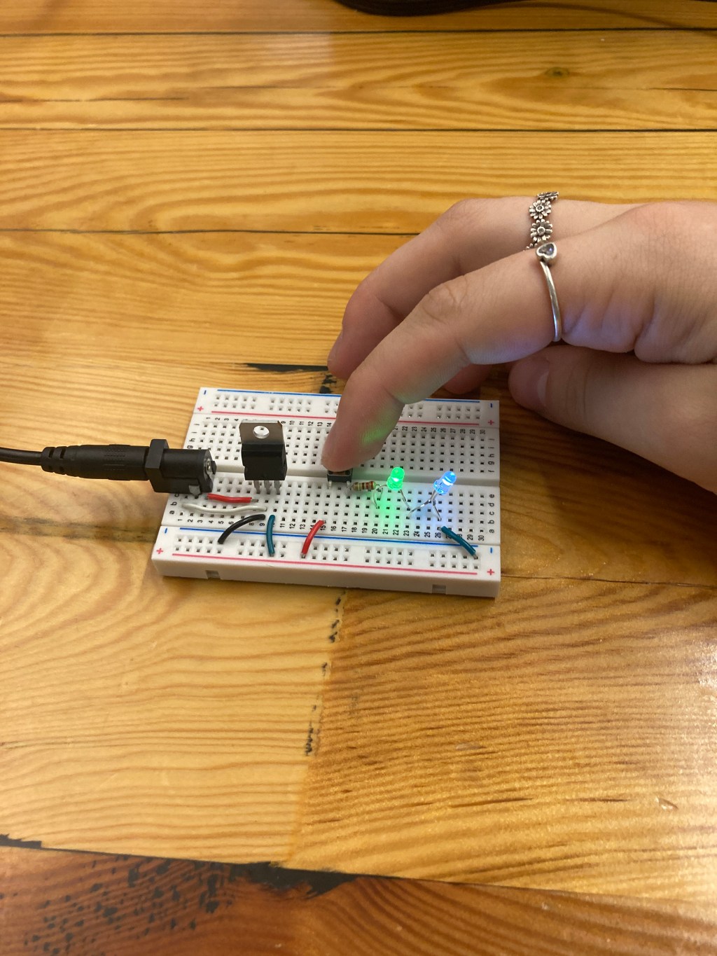
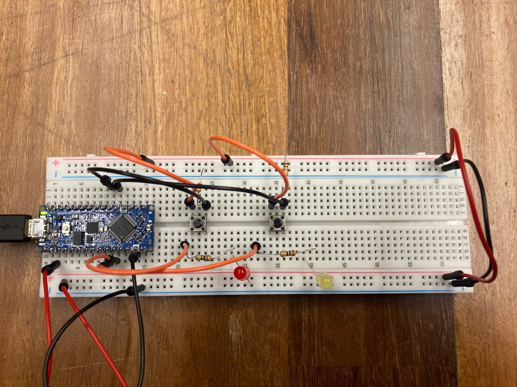
The closest resistor value to 65Ω was 47Ω, so I used that one. I then hooked up the power to the arduino board and originally accidentally wired the switches with the 47Ω resistors, but as I was testing the first LED that I hooked up I noticed that it turning on only sometimes. I realized what the problem was and fixed that so that the switches were hooked up with 10kΩ resistors instead. After this the LED was working correctly, so I added the second LED and changed the code so they had different colors when the different buttons were pressed. I then changed it so when both the buttons were pressed at the same time, it flashed both of them one at a time and then turned them both on.
int led1 = 21;
int button1 = 3;

int led2 = 20;
int button2 = 2;


void setup() {
  // put your setup code here, to run once:
  pinMode(led1,OUTPUT);
  pinMode(button1,INPUT);

  pinMode(led2,OUTPUT);
  pinMode(button2,INPUT);
}

void loop() {
  // put your main code here, to run repeatedly:
  int buttonState1 = digitalRead(button1);
  int buttonState2 = digitalRead(button2);


  if (buttonState1 == HIGH && buttonState2 == LOW){
    digitalWrite(led1,HIGH);
  }else{
    digitalWrite(led1,LOW);
  }

    if (buttonState2 == HIGH && buttonState1 == LOW){
    digitalWrite(led2,HIGH);
  }else{
    digitalWrite(led2,LOW);
  }

  if (buttonState1 == HIGH && buttonState2 == HIGH){
    digitalWrite(led1,HIGH);
    delay(250);
    digitalWrite(led1,LOW);
    delay(100);
    digitalWrite(led1,HIGH);
    delay(250);
    digitalWrite(led1,LOW);
    delay(250);
    digitalWrite(led2,HIGH);
    delay(250);
    digitalWrite(led2,LOW);
    delay(100);
    digitalWrite(led2,HIGH);
    delay(250);
    digitalWrite(led2,LOW);
    delay(250);
    digitalWrite(led1,HIGH);
    digitalWrite(led2,HIGH);
    delay(250);
    digitalWrite(led1,LOW);
    digitalWrite(led2,LOW);
    delay(250);
  }
}
Part 2: Digital I/O with a Programmable LED Strip
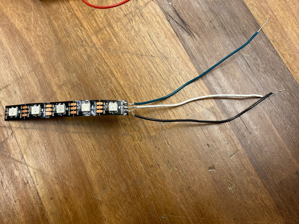
Since I had my wiring all set up for LED’S, it was really easy to swap the LED’s with my LED strip. I started by soldering my neopixel strip with 3 wires, one for power, one for ground, and one for connecting it to the arduino/circut. I attached it to my board then ran the sample program to make sure that my LED strip was hooked up correctly. Below is also the circut for this LED strip.

I then wrote code that used the buttons to change the output of the LED strips, where when I would press the first one it changed all the even pixels on to a blue color, and when I would press the second button it changed all the odd pixels on to a purple color. When I would press both of them at the same time it flashes on all the even pixels and then all the odd pixels.
#include <Adafruit_NeoPixel.h>
#ifdef __AVR__
#include <avr/power.h>
#endif
//define the digital pin that the LED strip is connected to
#define PIN 20
//button pins
int button1 = 3;
int button2 = 2;
Adafruit_NeoPixel strip = Adafruit_NeoPixel(5, PIN, NEO_GRB + NEO_KHZ800);
void setup() {
strip.begin();
strip.show();
pinMode(button1,INPUT);
pinMode(button2,INPUT);
Serial.begin(9600);
}
void loop() {
int buttonState1 = digitalRead(button1);
int buttonState2 = digitalRead(button2);
if (buttonState1 == HIGH && buttonState2 == LOW){
//even pixels on
Serial.println("reading red");
for(uint16_t i=0; i<strip.numPixels(); i+=2) {
strip.setPixelColor(i, 16, 130, 59);
}
strip.show();
}else{
//off
for(uint16_t i=0; i<strip.numPixels(); i++) {
strip.setPixelColor(i, 0, 0, 0);
}
strip.show();
}
if(buttonState1 == LOW && buttonState2 == HIGH) {
//odd pixels on
for(uint16_t i = 1; i<strip.numPixels(); i+=2) {
strip.setPixelColor(i, 69, 16, 130);
}
strip.show();
}
else {
for(uint16_t i=0; i<strip.numPixels(); i++) {
strip.setPixelColor(i,0,0,0);
}
strip.show();
}
if(buttonState1 == HIGH && buttonState2 == HIGH) {
for(uint16_t i=0; i<strip.numPixels(); i+=2) {
strip.setPixelColor(i, 16, 130, 59); //set to purple, takes RGB vals 0-255
strip.show();
delay(500);
strip.setPixelColor(i,0,0,0);
strip.show();
delay(500);
strip.setPixelColor(i, 16, 130, 59); //set to purple, takes RGB vals 0-255
strip.show();
delay(500);
}
//turn off on one at a time
for(uint16_t i=1; i<strip.numPixels(); i+=2) {
strip.setPixelColor(i, 69, 16, 130); //set to purple, takes RGB vals 0-255
strip.show();
delay(500);
strip.setPixelColor(i,0,0,0);
strip.show();
delay(500);
strip.setPixelColor(i, 69, 16, 130); //set to purple, takes RGB vals 0-255
strip.show();
delay(500);
}
}
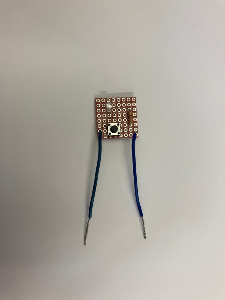
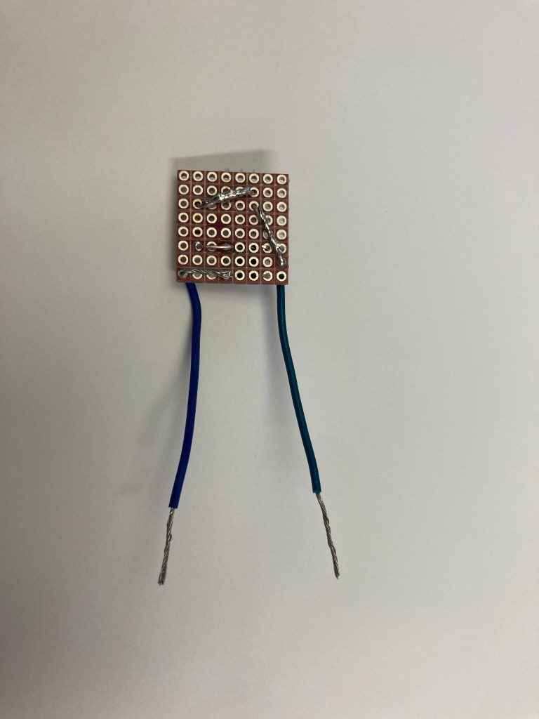
}Part 3: Soldered Breakout Boards
I chose to make a breakout board with a button and 2 LED’s. I did make a mistake though and chose purple LED’s which have too high voltage requirements so I couldn’t get both of them to light up even though they were both wired correctly. I removed the second one and re-soldered so it was just a button and one LED.

Leave a comment